Specify Shrinkage
In this section, you will learn how to apply shrinkage to a RefPart.
It exists 2 methods to apply the shrinkage:
A method that scales the complete model
A method to define each dimension one by one.
We may apply now a 5% shrinkage by scaleto the RefPart in all directions as follows:
Pick any model when you are prompted to select the model for the shrinkage,
Keep the following setups:
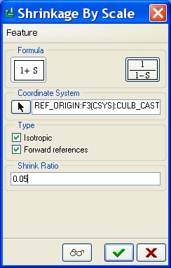
Select the coordinate system REF_ORIGIN in the model.
Validate the feature: a new feature is added at the RefPart level
Create the Workpiece
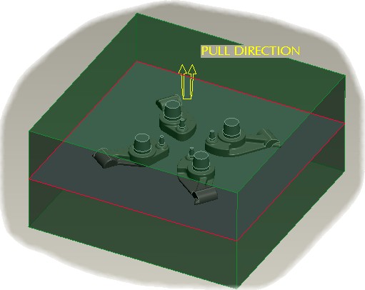
In this section, you will learn how to use the automatic workpiece creation: the workpiece is a bloc that will be split into several smaller volumes that will be the sand cores, core and cavity elements.
to create the workpiece.
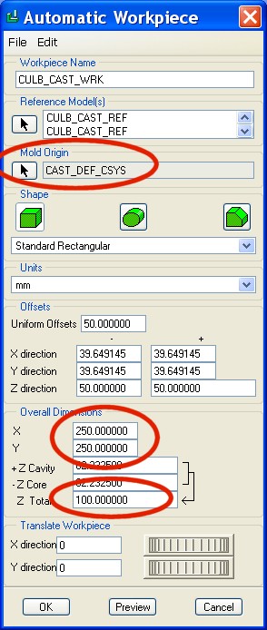
The Mold origin is the Cast Assembly default CSYS (CAST_DEF_CSYS)
We will set values for X, Y and Z:
X = 250
Y = 250
Z = 100
OK to validate the Workpiece creation.

Create Sand Cores
In this section, you will learn how to create sand core elements to fill holes and other small part details.
This Casting Assembly being quite simple, we will directly work and create the Sand Cores.
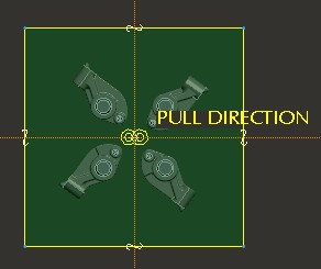
We will create directly a sand core model for each hole in the part. This new mode will be created as a Solid, and positioned with the 3 first planes of the 1st placed model in the cast layout.
We will create a Protrusion / Extrude to represent this 1st sand core.
Use SC_01 datum plane DMT3 as the sketching plane and then, use the edges of the bigger hole to represent a circle

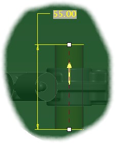

Use SC_01 datum plane DMT3 as the sketching plane and then, use the edges of the bigger hole to represent a circle
Make the protrusion a both sides 55mm cylinder
You may add 2 chamfers ( d x Angle ) at each extremity of the sand core

When the part is completed, activate back the assembly and pattern by reference the sand core: it will be placed 4 times in the model, one at each part location.
Reproduce the same things for a second sand core in the smaller hole.
Parting Surface
In this section, we will create a basic splitting surface: our example is really simple, and does not requires complex parting surface creation.
to start the parting surface creation. The select the Flat Surface.
Select MAIN_PARTING_PLN as the sketch plane, and then sketch a rectangle using the 4 edges of the workpiece to create a surface that will cut the complete workpiece into 2 models by its middle.