Set up the Cavity Layout
If any assembly is still loaded in Pro/ENGINEER close the current window with Window > Close and erase all models with File > Erase > Not Displayed.
Set the Working Directory
Set the working directory of Pro/ENGINEER with File > Set Working Directory. Browse to the path:
<installdir_tutorial>/models/asm_mode.
an press OK.
Load the Model
Press File > Open..., select the assembly TUTOR.ASM and Press Open.
Define the Cavity Layout
Press EMX > Mold Base > Assembly Definition.
Click to open the Cavity dialog box.
Click Rectangular as Cavity pattern type.
Enter Quantity 2 in the Y-column and Pattern size 120.
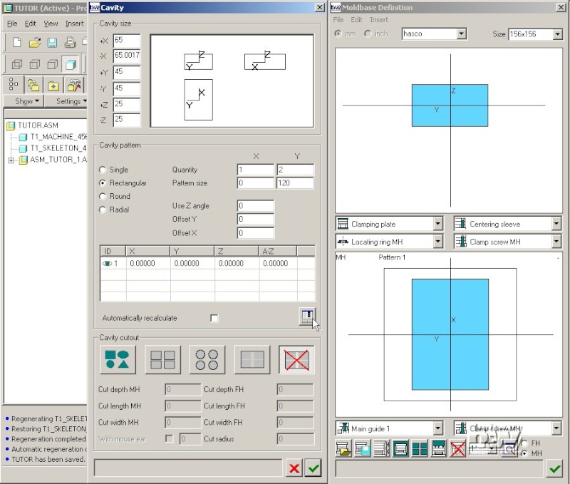
Press to update the pattern instance list. The result is immediately updated in the Moldbase Definition dialog box.
Modify the Cavity Layout
Double click the A-Z column of the second instance line and enter 90.
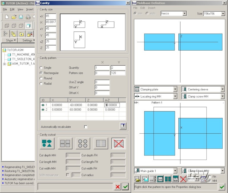
Enter Quantity 2 and Pattern size 120 for the X-column and press .
Note: If you have activated the button Automatically recalculate the pattern list will be updated without pressing .
Click the icon in the third line. It will change to and the instance disappears in the Moldbase Definition preview.
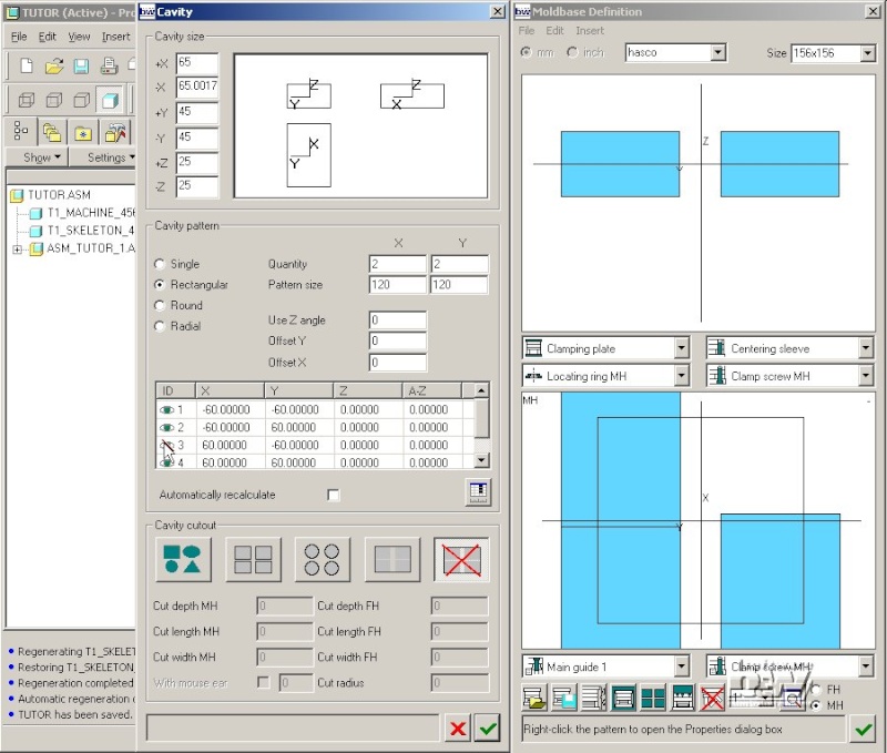
Note: This manipulation options are available for all patterns in EMX dialog boxes.
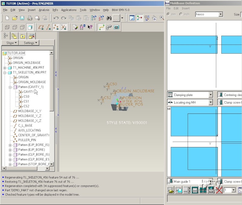
Update the Cavity Layout in the 3D model
Just get in touch with this way of defining a pattern by doing some more modifications. Finally set the pattern like this:

Press to close the Cavity dialog box.
EMX will regenerate the setting now in the 3D model TUTOR.ASM.
Note: For some patterns (if the first instance has negative values for X and Y) the regeneration might not be 100% correct after the first regeneration. In this case open the Cavity dialog box again and close it with , then the pattern dimensions should be ok in the 3D model.
Assemble a second Cavity Insert Assembly
Open the Cavity dialog box with .
Enter Quantity 1 and Pattern size 0 for X.
Press .
Press to close Cavity dialog box.
Close the Moldbase Definition dialog box with .
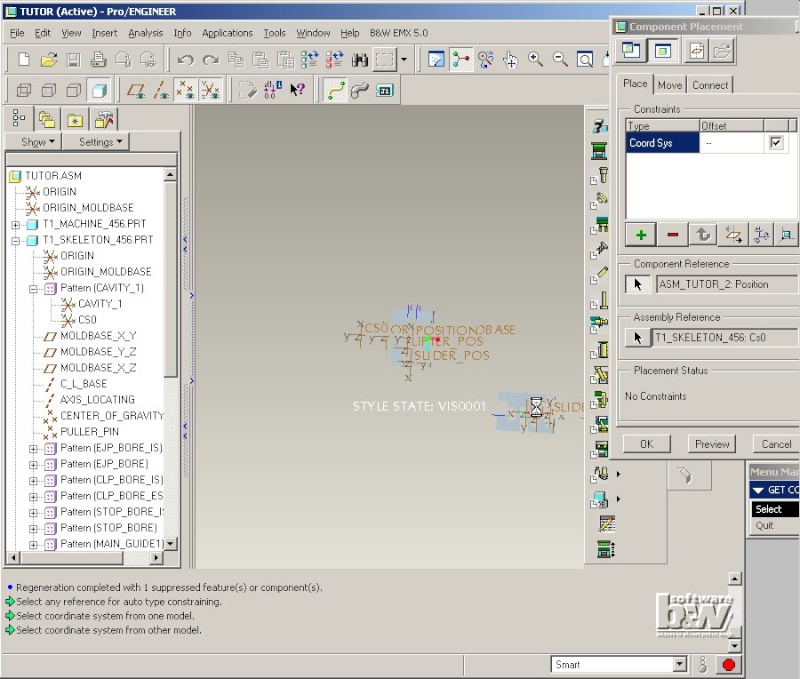
Select Insert > Component > Assemble.
Open the second instance of the cavity insert assembly ASM_TUTOR_2 and assemble it with Csys POSITION on the CS0-Csys of the skeleton model.
Note: If the cavity insert can be identical on all instances of the layout just create a reference pattern of the first instance ASM_TUTOR_1.
Press EMX > Project > ...classify. All settings are correct immediately, no modification is required.
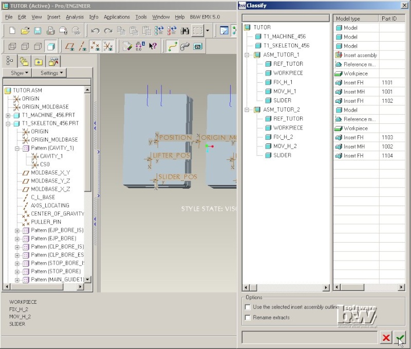
Close the Classify dialog box with .
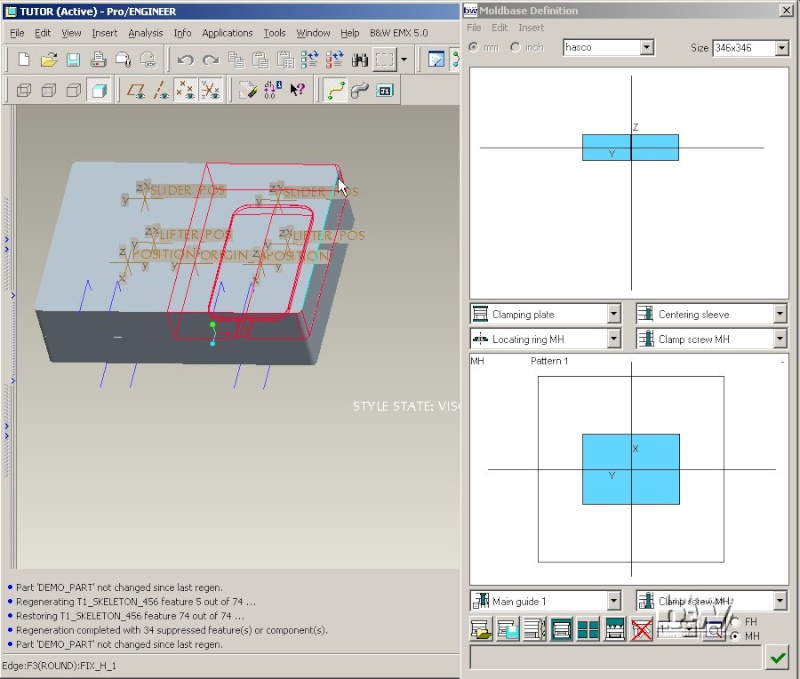
Modify the Moldbase Size
Press EMX > Mold Base > Assembly Definition.
From the Size list select entry 296x446.
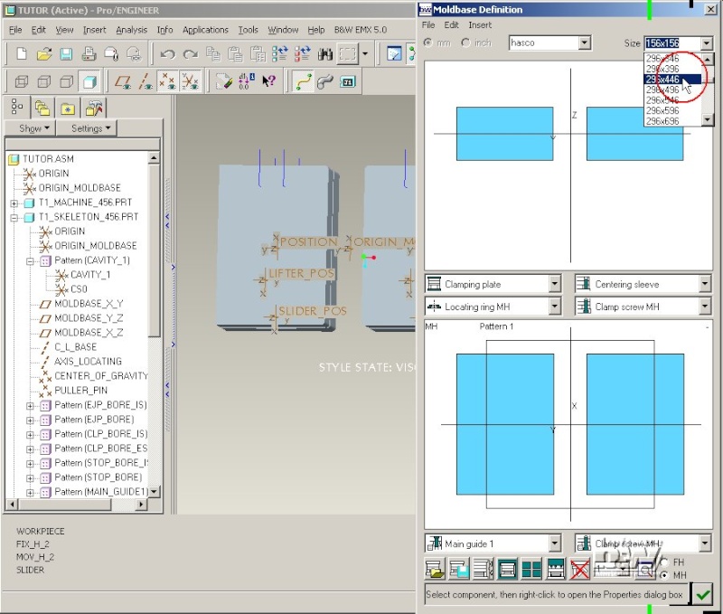
Prompt the EMX Question Use this size and update all existing components with (Yes). The outline in the top view of the Moldbase Definition is updated so the placement of the cavity inserts can be verified.
Note: At this point the skeleton datum planes and axis will be set to the according positions. As no further components are assembled right now this happens rather fast. Once all EMX moldbase components are assembled all of them will be regenerated. This modification of the moldbase size is the most critical modification that can be made in a late state of your design process, so be careful when using that.
Select Size 346x346 and prompt with (Yes).
Open the Cavity dialog box with .
Enter Pattern size 90 for Y.
Press .
Change the A-Z value for both lines to 180.
This will rotate the cavity inserts so that their predefined radii at the corners fit to the corners of the cavity cutout.
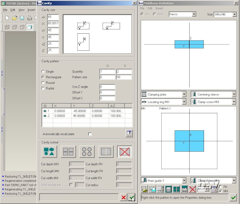
Press to close the Cavity dialog box.
The resulting 3D model should look like this:
Close the Moldbase Definition dialog box with