Manipulate Screws, Stop Pins, Return Pins
Modify pattern for clamping screws
Press EMX > Mold Base > Assembly Definition.
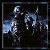
Rightclick any pattern member of the clamping screw MH pattern to open the according pattern dialog box Clamp screw MH. (see red circle in image below) or select Edit > Pattern > Clamp screw > MH from Moldbase Definition menu.
Enter Value 3 in X Quantity.
Press to update the pattern instances.
Click first column of instance four to set it invisible .
Double click the X-column of the third instance and enter 40
 https://i.servimg.com/u/f48/12/18/64/76/03_5110.jpg
Check the preview in the top view of the Moldbase Definition before pressing .
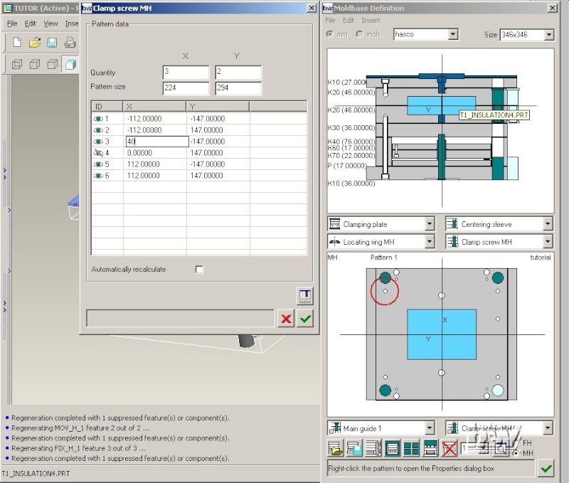
The 3D assembly gets regenerated.
Note: As such pattern modifications affect both the skeleton model and all plates the regeneration takes longer for such a modification.
Remove Stop Disc
Close the Moldbase Definition dialog box with .
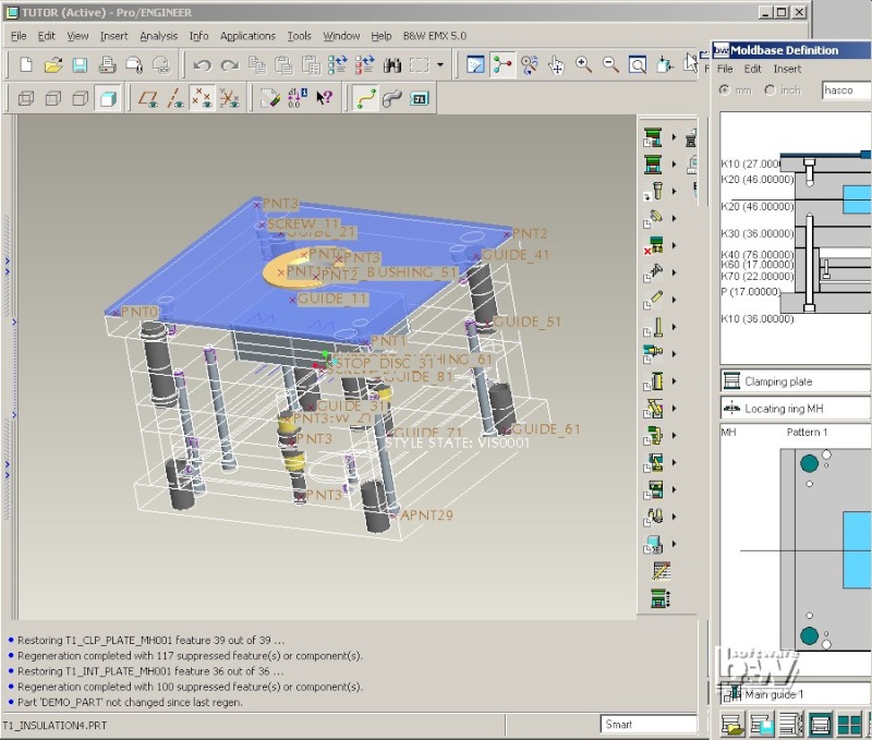
Select EMX > Stop System > ...delete.
Click datum point STOP_DISC_31.
Press (Yes) in the EMX Question dialog box.
The stop disc assembly T1_STOP_ASM3 is deleted. As the tapped hole to assemble this component was defined in the plate properties it will remain. Read To Cut or Not To Cut. This must be removed by modifying the plate features in the Plate dialog box.
Press EMX > Mold Base > Assembly Definition.
Rightclick the K70 plate in side view.
Click the STOP_THREAD_BORE feature so it becomes .
Leave the Plate dialog box with .
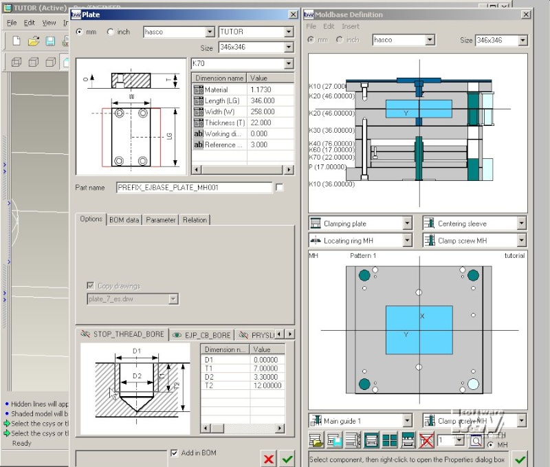
The feature STOP_THREAD_BORE of the ejector base plate T1_EJBASE_PLATE_MH001 is suppressed.
Note: If you would run the function EMX > Project > ...finish at this point this (and all other suppressed features) would be deleted in all EMX plates. There is no way to restore this feature after that, if you reenter the plate dialog box all deleted features are no longer displayed in the feature area.
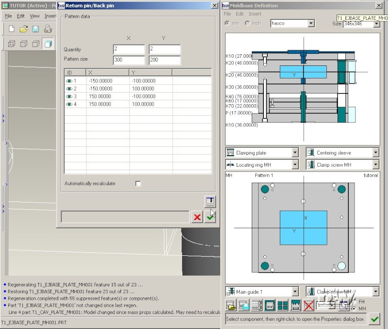
Define the Return Pin Pattern
Select Edit > Pattern > Return pin/Back pin (or select Return pin/Back pin from the Clamp screw MH pattern list).

Set X and Y Quantity to 2.
Enter Pattern size 300 and 200.
Press .
Close the Return pin/Back pin pattern dialog box with .
Define the Return Pin Properties
Select Insert > Return pin/Back pin (or select Return pin/Back pin from the Clamp screw MH component list shown with red circle below).
The Reference Distance in the Ejector Pin dialog box is set automatically (116). This is the distance between the bottom side of the ejector retainer plate and the datum point RETURN_PIN of the EMX assembly skeleton.
Double click Diameter Value and select 10.0.
EMX will find the first instance of the ejector pin with that length (125) that exceeds the required reference distance of 116.
Click BOM data and check wether the ordering number is ok.
Now the Return pin is also displayed in the side view of the Moldbase Definition. Check if the dimensions for the UDF's are ok.
Note: Click the Dimension name column in the UDF area to highlight the dimension in the Overview image.
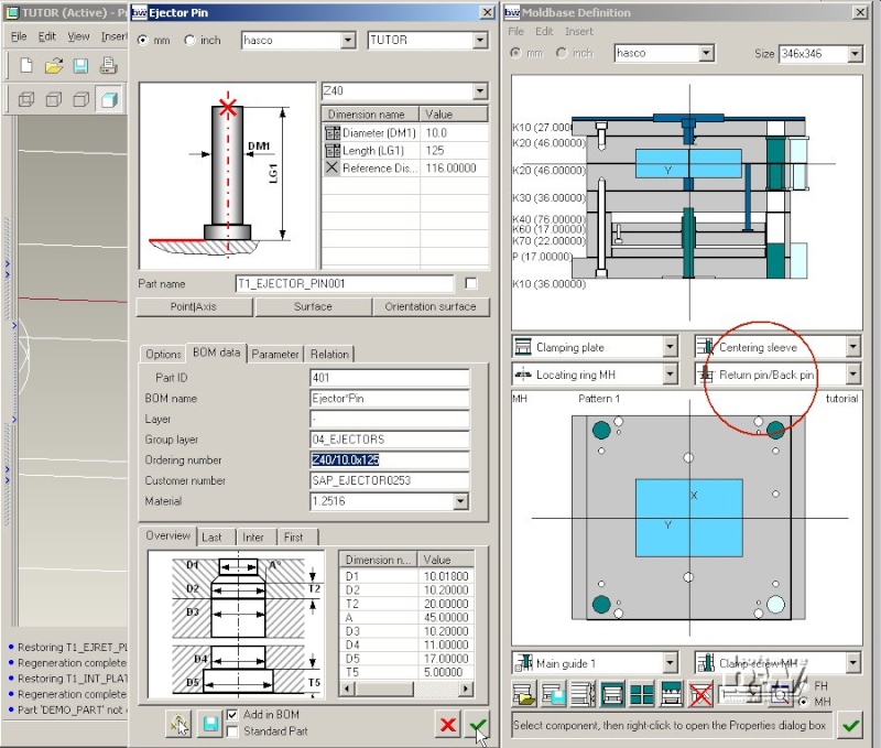
Close the Ejector pin dialog box with .
The ejector pins are assembled as a reference pattern on the previously defined positions, the required cutouts in the plates are created using the UDF dimensions.

Close the Moldbase Definition dialog box with .
Save the assembly TUTOR.ASM for later use with File > Save.
Watch movie