Manipulate Equipment Components
Delete the Insulation plate in Moldbase Definition
Press EMX > Mold Base > Assembly Definition.
Select in Moldbase Definition.
Select the insulation plate of the fix half.
Click (Yes) in the EMX Question dialog box.
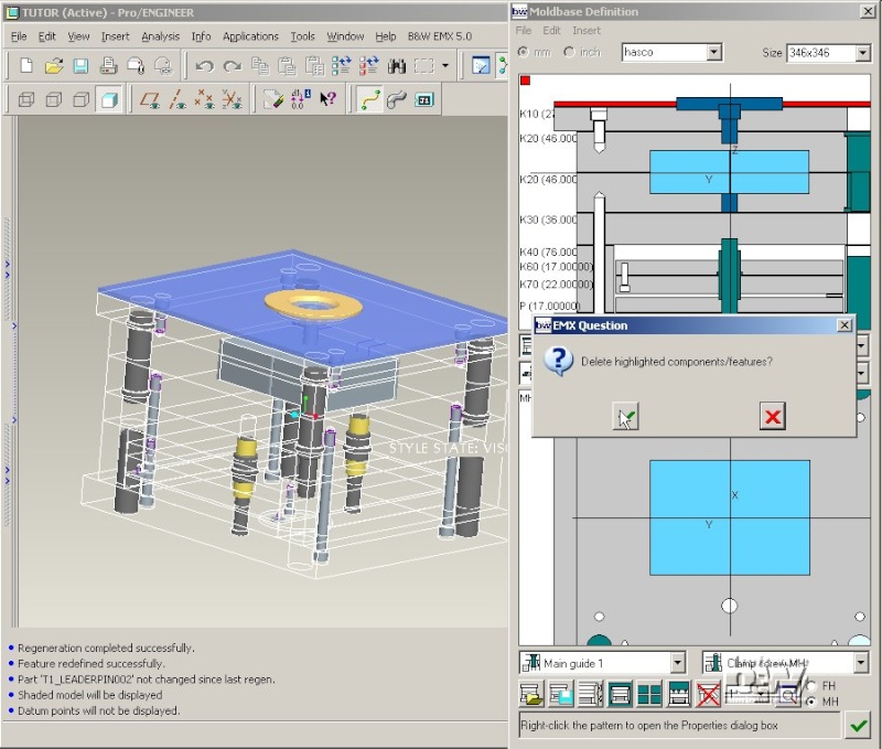
Close the Moldbase Definition dialog box with .
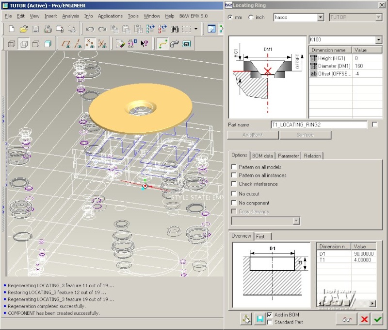
Modify the Locating Ring
After the insulation plate was deleted the height of the locating ring does no longer fit.
Select EMX > Equipment > ...modify.
Select the datum point LOCATING_21.
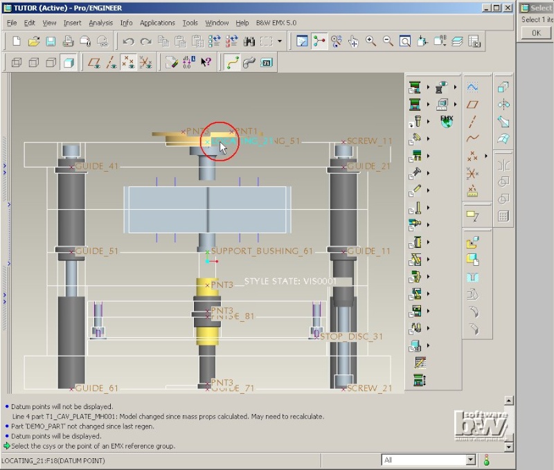
The Locating Ring dialog box is opened.
Double click the Height Value and select 8 from the list.
Double click the Diameter Value and select 100 from the list.
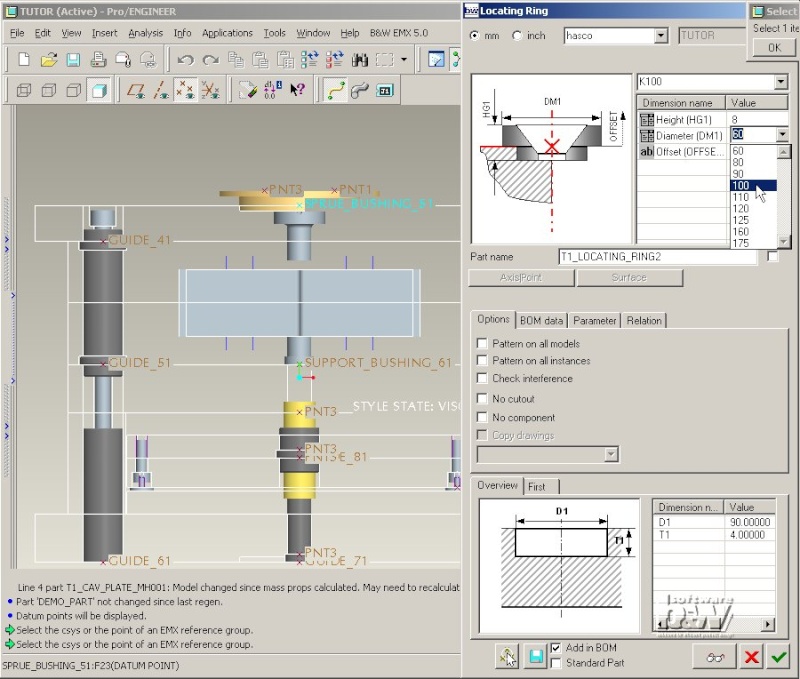
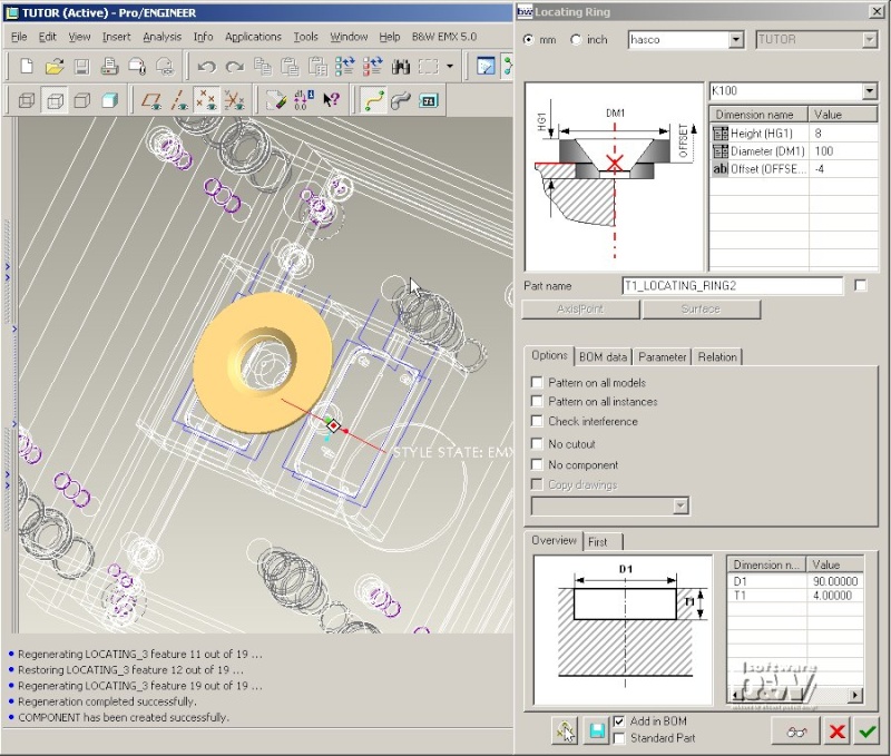
Click the preview button .
The entire 3d assembly is set to wireframe mode.
The existing locating ring is suppressed(!) and the locating ring with the new dimensions is assembled and displayed in shaded more.
Note: While EMX displays a preview of any component the Save and Save As buttons of Pro/ENGINEER are deactivated. This avoids undesired saving of intermediate states. The component that is displayed in preview is the original template.
Double click the Diameter Value and select 160 from the list.
Click the preview button again to check the new dimension.
Close the Locating Ring dialog box with .
The preview model is disassembled again. The previous model T1_LOCATING_RING2 will be resumed again and set to the new dimensions.
Note: If you have modified the component type (so that the geometry has to be realized using a new locating ring template) or if the checkbutton Standard Part in the Locating Ring dialog box is active, EMX will not simply modify the dimensions of the existing locating ring but it will substitute the model of the component with a new instance from the database. This "substituting" make sure that no component related information is deleted. For INTRALINK or PDM/Link users this behaviour is required to replace the existing instance of a component with a new instance from the database.
Define the Side Interlock Pattern
Like any other EMX components equipment such as Locating Rings, Sprue bushings etc.. can be defined using the function EMX > Equipment > ...define xxx. For some types of equipment such as Side Interlocks, Toplocks or Return pins it is more useful to define them in the Moldbase Definition dialog box as they are placed on patterns that can be maintained from this dialog box.
Open Moldbase Definition with EMX > Mold Base > Assembly Definition.
Note: The wrong placement of a leader pin shown in the Movie is an error that should not occur with your EMX5.0 M020 release.
Select the Side Interlock pattern from the pattern list in the bottom right corner of the dialog box (see red circle in image).
The Pattern size values in the Side interlock dialog box are set to the current moldbase size by default.
Enter Quantity 2 in Y-direction.
Press to update the number of instances.
Note: The internal calculation of a side interlock pattern differs from the calculation of axis patterns such as clamping screw, leader pin etc. Check the placement of the Side Interlocks in the top view of the Moldbase Definition dialog box.

Check more default pattern layouts supported by EMX ...
Enter Y Quantity 3 and press .
Click the icon in the third line so it becomes .
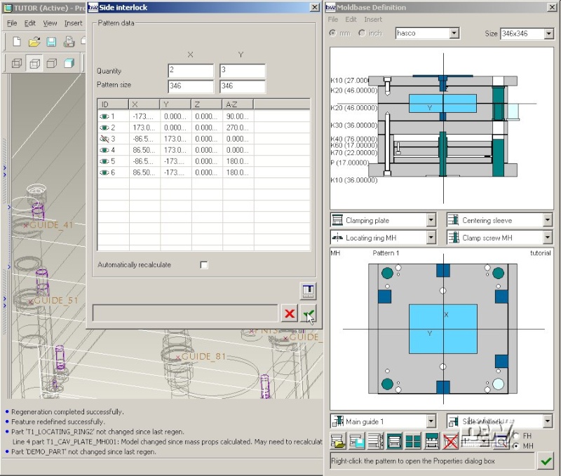
Press to regenerate the pattern in the EMX skeleton model.
Rightclick any pattern member in the top view of the Moldbase Definition to reopen the Side interlock dialog box.
Finally set the Y Quantity to 2 again and press .
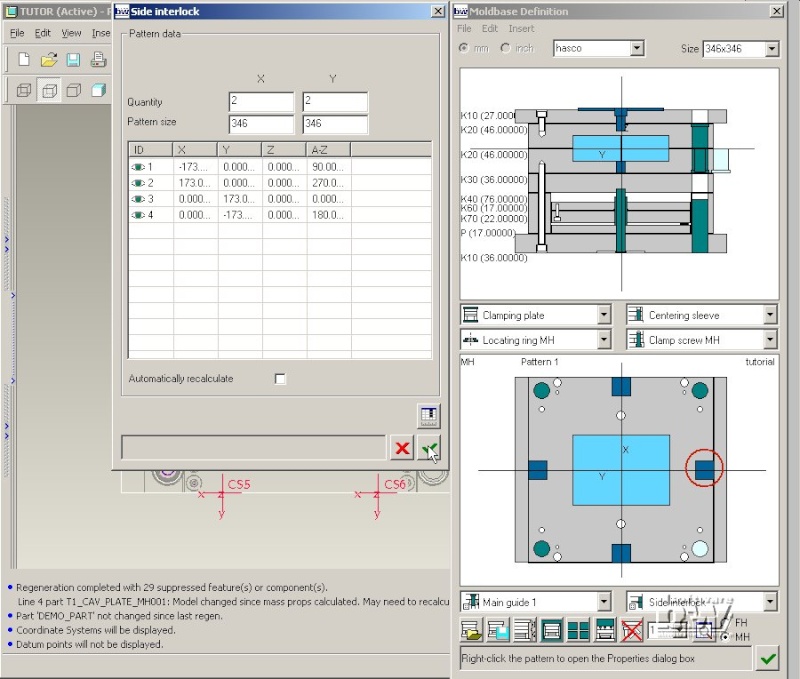
Close the Side interlock pattern dialog box with .
Define the Side Interlock Properties
Select Side Interlock from the Equipment pull down list (the default entry is Locating Ring MH).
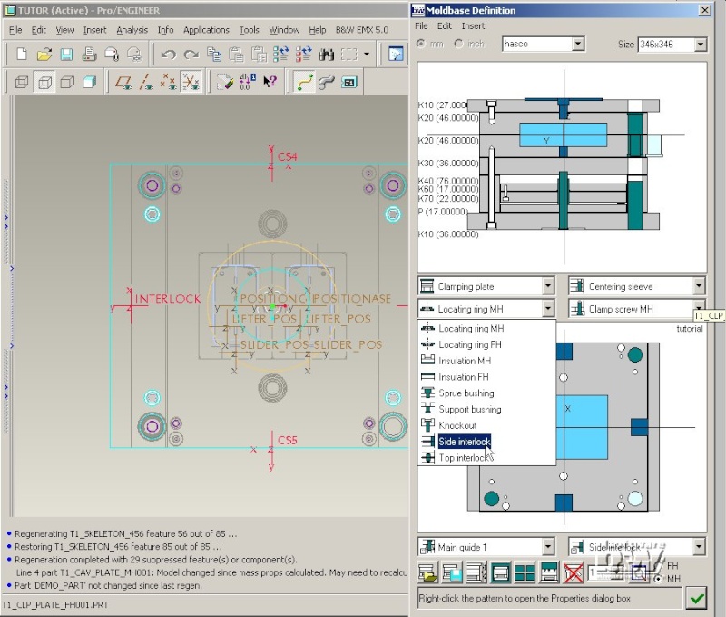
Do not change any default settings in the Side Interlock dialog box.
Note: Side interlock components create their cutouts using a Cut by Surface feature. In this case just one Overview image is displayed in the UDF area.

Press to close the Side Interlock dialog box.
Close the Moldbase Definition with .