MFG mode: Prepare Classify Components
Open the Manufacturing assembly TUTOR_MFG.MFG with File > Open.
Press the button to invoke the Blank - Unblank dialog box and blank the Visible Component TM1_WORKPIECE_456 and the Visible Surface PART_SURF_1.
Press Close.
Press Window and select TUTOR_MFG.ASM to make the assembly the active model again.
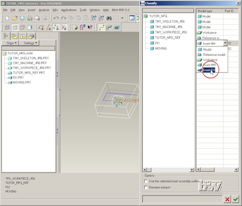
Press EMX > Project > ...classify to open the Classify dialog box.
Double click the Model type column of the part FIX and select Insert FH from the list.
Click Use the selected insert assembly outline.
Press .
EMX will not measure the size of the Extracts in Manufacturing mode. It will determine the bounding box of the part TUTOR_MFG_REF classified as Reference model.
Open the Moldbase Definition with EMX > Mold Base > Assembly Definition. The blue box represents the reference model size in this case.
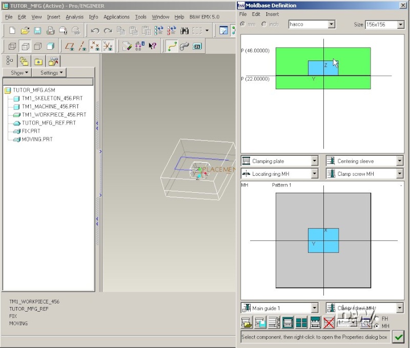
Press to open the Cavity dialog box. This dialog box can be used to layout the reference model pattern.
Close the Cavity dialog box with .
Close the Moldbase Definition dialog box with .
Create the EMX Moldbase
All further steps in moldbase design will be explained based on ASM-mode assembly TUTOR.ASM. The moldbase in EMX is the stack of plates including all standard parts that are usually shipped as one unit by the moldbase suppliers.
Create/Modify/Delete Plates
Add one Cavity Plate
Press EMX > Mold Base > Assembly Definition.
Select Cavity plate from the plate list (the default plate displayed in this list is Clamping plate)
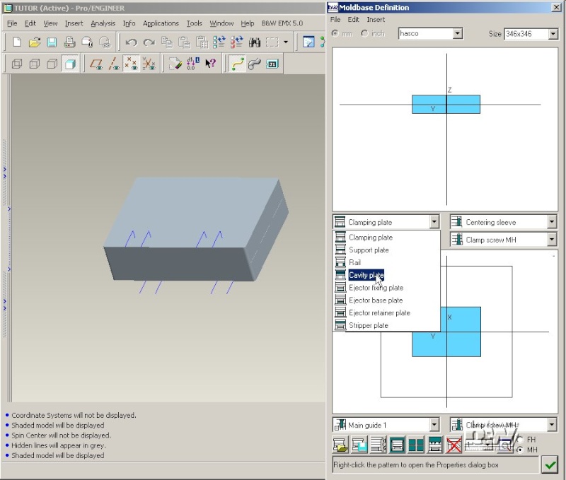
Note: All functions can also be accessed from the Moldbase Definition menu. For adding a plate use Insert > Plate > Cavity plate. It is much faster using the EMX icons, therefore the according menu entries will not be mentioned in this tutorial.
A green rectangle appears in the top left corner of the upper view to indicate that you have to select a position with the left mouse button. If no plate exist just click above or below the splitting plane to define a Cavity Plate Moving Half (b-plate) or Fix Half (a-plate).
Pick below the splitting plane.
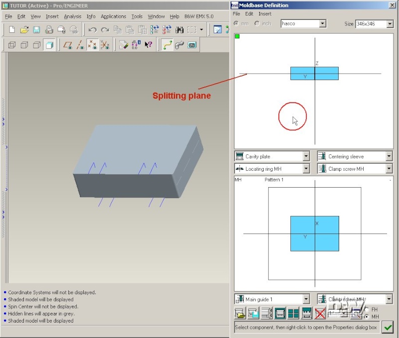
The new plate is displayed in Moldbase Definition preview and the Plate dialog is opened.
In the movie you will see the content of the BOM data, Parameter and Relation Register.
Double click the Thickness Value and select 46.000 from the list.
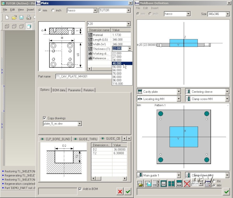
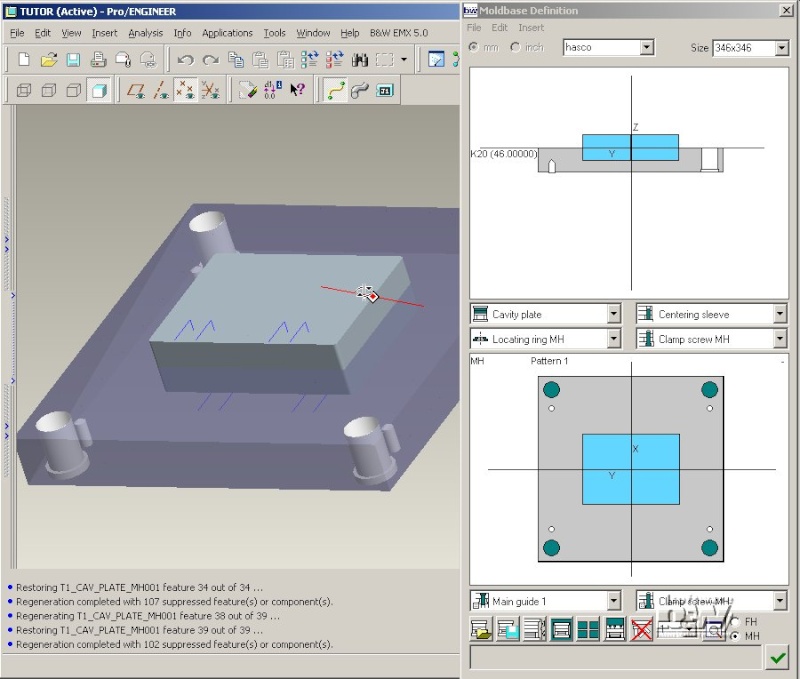
The modified thickness can be checked immediately in the Moldbase Definition preview.
Close the Plate dialog box with . The plate will be added in the EMX assemble.
Resume suppressed Plate Features
Open the Plate dialog box for existing plates by clicking them in the side view of Moldbase Definition with the right mouse button [Rightclick].
The features of the plate are listed in the bottom area of the Plate dialog box. Icons indicate which features are suppressed and which features are resumed .
Scroll the list to the right using the arrow buttons until you see the CHAMFER entry. Click on the icon . It will change to .
Double click the Value column of the Dimension W1 and enter 2.
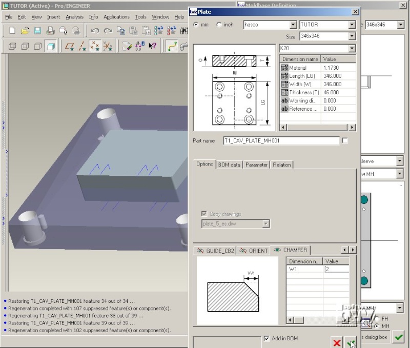
Close the plate dialog box with .
EMX will resume the feature CHAMFER in the plate T1_CAV_PLATE_MO001.PRT and set the dimension with symbol name W1 to 2.
Modify Resumed Plate Features
Rightclick the K20 plate in Moldbase Definition again.
Double click the T2 Value of the CLP_BORE feature and enter 35.
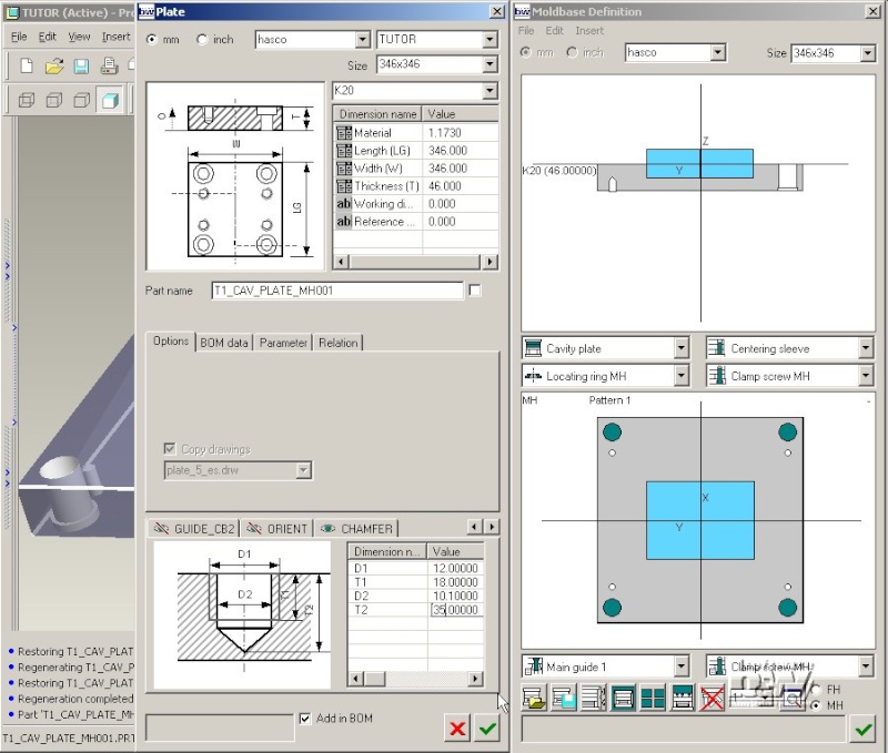
Close the plate dialog box with .
The core depth of the tapped hole in the plate T1_CAV_PLATE_MO001.PRT is set to 35 mm.