ASM Mode: Prepare/Classify components
Why must components be classified
For functions like ejector pin trimming or ejector pin cutout placement EMX needs to know which part of the insert assembly is the reference model and which parts are the extracts of the Moving and Fix Half in your moldbase. EMX will also avoid any modification in the Pro/MOLDDESIGN Workpiece that might be part of the insert assembly. So it is very important to use the function EMX > Project > ...classify.
The second reason why EMX provides this function is the ability to measure the bounding box of all extracts in the insert assembly. This bounding box can later be used for cavity layout and to select a proper size of the moldbase.
Press EMX > Mold Base > Assembly Definition. No box or representation of the cavity insert is shown. Close the Moldbase Definition dialog box with again.
Use the Classify dialog box
Press EMX > Project > ...classify to open the Classify dialog box. Similar to the Pro/ENGINEER model tree all components are shown in a tree structure. By default EMX is able to identify the Model type for some of them (i.e. the reference model, the workpiece) automatically.
Double click the column Model type of the ASM_TUTOR_1 assembly.
Select Insert assembly from the list.
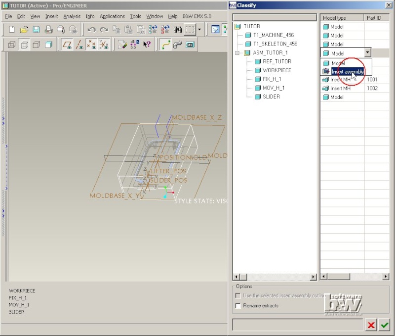
The button Use the selected insert assembly outline will be enabled. Click on this button to activate it.
Double click the column Model type of the FIX_H_1 model.
Select Model type Insert FH.
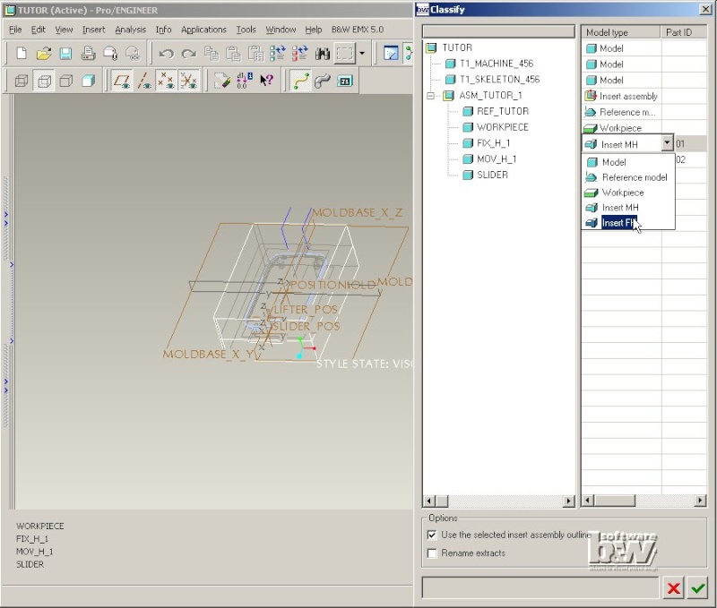
Set the Model type for the SLIDER-part to Insert MH in the same way.
Save the settings by pressing . EMX will determine the outline of all parts classified as Insert MH and Insert FH in the assembly classified as Insert assembly. This measurement can be done for one insert assembly only. If you have more than one insert assemblies with different sizes in your moldbase you have to decide which one of them is the Insert assembly used for measurement.
All parts classified as Insert MH will be placed on the Layer and Simplified Representation 00_MOVING_HALF (set by the EMX option NAME_MOVING_HALF), all Insert FH part are set on 00_FIX_HALF.
Use the outline in Moldbase Definition.
Press EMX > Mold Base > Assembly Definition. Now the size of the cavity insert is displayed as blue box to allow proper layout. Press to open the Cavity dialog box.

Press to leave the dialog box and save the assembly (for later us in this tutorial) with File > Save.
Additional Project Functionality
If the EMX manufacturing assembly TUTOR_MFG from the previous chapter is still loaded in Pro/ENGINEER close the current window with Window > Close and erase all models with File > Erase > Not Displayed.
Set the Working Directory
Set the working directory of Pro/ENGINEER with File > Set Working Directory. Browse to the path:
<installdir_tutorial>/models/asm_mode.
an press OK.
Load the Model
Press File > Open..., select the assembly TUTOR.ASM and Press Open.
Modify Project settings
Press EMX > Project > ...modify.
Initially this project was created with local project parameters. So a file exist in this working directory named project_parameter.cfg.

Click Add local project parameters to deactivate this option.
Enter a new Note text This is just a parameter and I have modified it.

Press . The file project_parameter.cfg will be removed from the working directory and the new modified Note text is stored as parameter in the assembly.
Press EMX > Project > ...modify again.
Click Add local project parameters to activate this option again and select the Value AB-123 for the ARTICEL parameter.
Close the dialog box with .
EMX will create the file project_parameter.cfg again.
Use Modify project to rename the assembly or all components
If you overwrite the Project name during modify the EMX assembly, drawing, report (and optional Manufacturing model) will be renamed using the new name.
If you overwrite the Prefix or Postfix all components (and related drawings) of the EMX assembly that have the previous string in their partnames will be renamed using the new values.
Remove hidden/suppressed plate features
EMX plate templates are shipped with several suppressed features that represent required geometry of such a plate (i.e. cutout for locating ring, counter bore for clamping screws etc...). Press EMX > Project > ...finish to delete all suppressed features from all EMX plates in the current assembly. Use this function with care. Once the suppressed features have been removed from the EMX plates some changes of their geometry are not longer possible.
Use a previous designed EMX assembly
If the EMX assembly TUTOR from the previous chapter is still loaded in Pro/ENGINEER close the current window with Window > Close and erase all models with File > Erase > Not Displayed.
Deactivate the EMX Style option
Click EMX > Options. Click NAME_COMP_DISPLAY and enter Value -. Press Modify and to close the dialog box.
Create the EMX Project
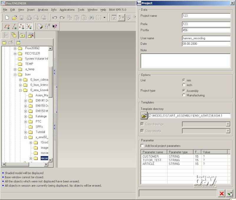
Press EMX > Project > ...create new.
Click to open the Select assembly template dialog box. Open the assembly EMX_ASM1234.ASM from the directory <install_tutorial>/models/start_assembly. This assembly was designed with EMX before.

Click Open. The full path to the chosen assembly is written to the Template directory entry. In this case any drawing or report files will be copied from the selected directory, so the options Copy drawings and Copy reports are disabled.
Click Add local project parameters to deactivate the option and press .
EMX will copy all files from the template directory and rename them using the new Project name, Prefix and Postfix. All related drawings will also be copied and renamed.

Open the drawing 123.drw. On the third sheet you will find the BOM table made by EMX.
You will recognize that the values in the PARTNAME column still show the previous part names. To update this column Press EMX > Bill of Material. In the EMX Bill of Material dialog box you will see the correct parameter values.
Close the dialog box with .
Check the drawing table to see that everything is ok now.