MFG mode: Create a Project starting with the article
If the EMX assembly TUTOR from the previous chapter is still loaded in Pro/ENGINEER close the current window with Window > Close and erase all models with File > Erase > Not Displayed.
Set the Working Directory
Set the working directory of Pro/ENGINEER with File > Set Working Directory. Browse to the path:
<installdir_tutorial>/models/mfg_mode.
an press OK.
Load the Model
Press File > Open..., select the part MFG_PART.PRT and Press Open. The Core/Cavity for this simple model should be design directly in the cavity plates of the moldbase assembly. In this case the Manufacturing mode of EMX can be used.
Create the EMX Project
Press EMX > Project > ...create new.
In Project dialog box...
Enter Project name TUTOR_MFG.
Enter Prefix TM1.
Select Project Type Manufacturing.
The default path for the Template directory will switch to .../mfg/empty_template.
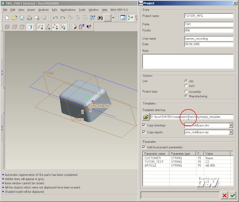
Click Copy drawings, Copy reports and Add local project parameters to deactivate all.
Leave the dialog box with .
EMX will copy the selected assembly template and its related manufacturing model from the template directory to the current working directory. Both models are renamed to TUTOR_MFG.
As the option NAME_COMP_DISPLAY is set to VIS0001 a new rule based style is added to the assembly with the name VIS0001. This rule will make sure all EMX plates are set to wireframe. To avoid the generation of this style set the option NAME_COMP_DISPLAY to -.
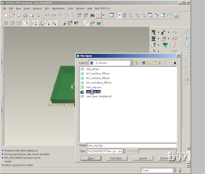
The EMX Machine model and Skeleton model are part of the template. In the Manufacturing template you will also find the MOLDDESIGN workpiece named TM1_WORKPIECE_456. To proceed with the regular tasks of the Core and Cavity design open the Manufacturing model TUTOR_MFG.MFG with File > Open.
Create the Core/Cavity with Pro/MOLDDESIGN
Click and chose MFG_PART.PRT in the Open dialog box. Do not change any entries in the Create Reference Model dialog box and press Ok.
Press Ok in the Layout dialog box and confirm the setting of absolute accuracy in assembly TUTOR_MFG.
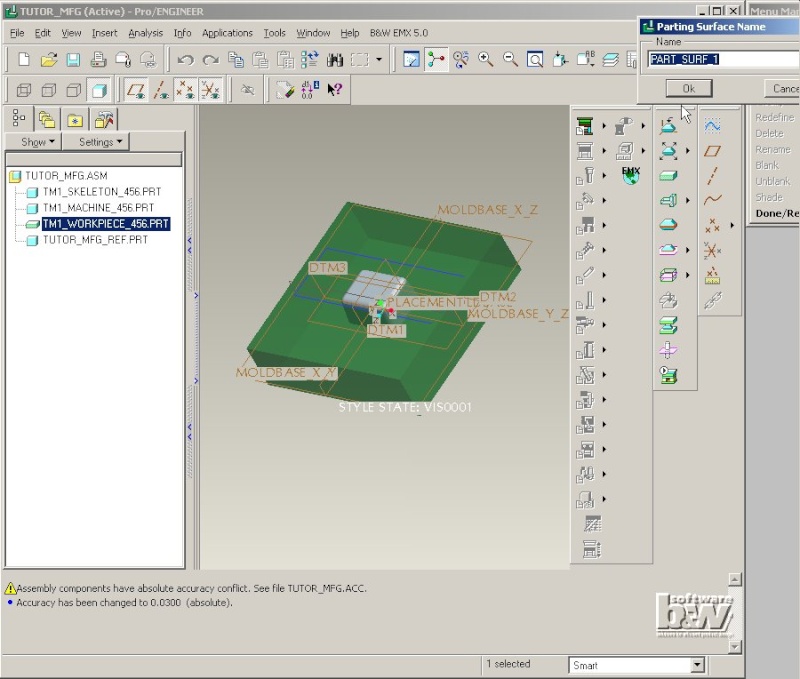
The article is assemble in the center of the workpiece.
Press MOLD > Parting Surface > Create.
Use the default Name PART_SURF_1 and press Ok.
Select Add > Flat > Done. And sketch a flat parting surface on the datum plane MOLDBASE_X_Y using the side faces of the workpiece.
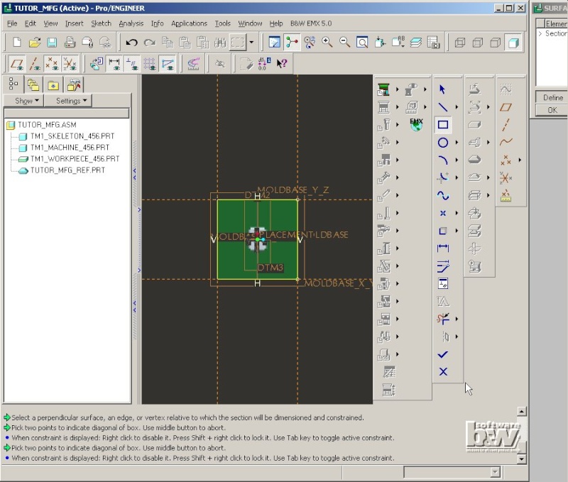
Exit sketcher with Ok, press Ok in the Surface Flat dialog box and press Done/Return twice.
Click . In SPLIT WORKPIECE select Two Volumes > All Wrkpcs > Done.
Select the parting surface PART_SURF_1 in the graphics window and press OK in the Select dialog box.
Select Island 1 to activate it.
Press Done Sel.
Press OK in the Split dialog box.
Enter Volume Name FIX for the first volume, press Ok.
Enter MOVING for the second volume and press Ok.
Select . Select both Mold Volumes in the Create Mold Component dialog box.
Press Ok.
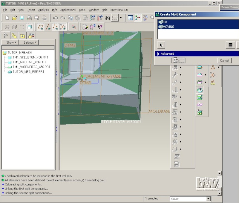
Two new models MOVING and FIX will appear in the model tree.
To enable EMX functionality open the Assembly TUTOR_MFG.ASM again.
Select EMX > Mold Base > Assembly Definition. The workpiece of the assembly is displayed as two green P-plates in the Moldbase Definition dialog box. They are 22 mm thick by default.

Click the upper P-plate with the right mouse button [rightclick] to open the Plate dialog box. Double click the Value Column of the Thickness entry and select 40.000 from the list.
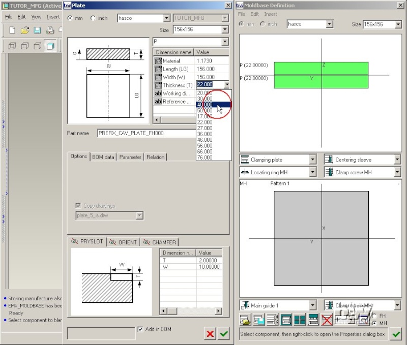
The modification is displayed in the preview. Leave the Plate dialog box with . EMX will set the new dimension in the EMX Workpiece and regenerate it. To update the modification in the extract models FIX and MOVING press .
Note: The EMX workpiece model has no further features included (like clamping screw tapped holes or leader pin cutouts). Even if you chose plate type K20 that should generate such features in the FIX and MOVING extracts they will not appear. You have to add the leader pins and clamping screws first, then the required cuts will be created in the extract models. Refer to To Cut or not To Cut to learn more about this behaviour.
Close the Moldbase Definition dialog box with .