In this section, we will create additional information to represent the casting hole (the metal should come in the cast right?).
It exists several methods to do so: we could create another "sand core like" component, or a cavity inserts, or cut the workpiece... or add runners. In this example, we will create an Assembly cut in the workpiece (it MUST be an assembly cut).
Insert > Revolve...
This is a CUT
Select datum plane CAST_RIGHT as the sketching plane,
Sketch some material reservation (a lot of retract in castings)
Create runners to connect the cut to the the parts
Insert > Runner...
Select Half Round,
Runner Diameter is 5 mm,
Sketching Plane is "MAIN_PARTING_PLN",
Sketch as follows:

The only part that is intersected is the Workpiece.
You may add other volumes to respect the thumb rules that says that there should be as much material in the reservations than in the part themselves...
Splitting the Cast Assembly
In this section, we will split the cast assembly.
to start splitting the Cast Assembly.
The split will be simple and in 2 parts.
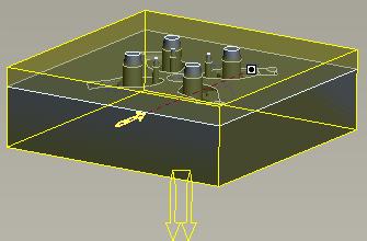
Select the flat surface we have created earlier as the split surfaces
and name the volumes...
the volume on the top:


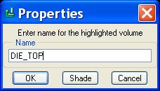


the volume on the top:
The Volume on the bottom (you may push SHADE before OK)
to extract the components: create actual Pro/E Parts from the volumes.
Press OK.
The 2 models DIE_TOP.PRT and DIE_BOT.PRT are now created.
We may now create the CAST RESULT:
From the side menu: Cast Model > Create > Cast Result,
Part name will be CULB_RESULT
Open the model to check it...

Creating the Wood Plates (Fixtures)
In this section we will create the wood plates used to form the sand for the cat mold... the cast mold shapes, as we have extracted them, might be machined, but, most of the case, a wood plate will be created to form the sand as it is compressed to create a new cast mold.
From the side menus:
Cast Model > Create > Fixture,
create it as a SOLID PART named BOT_PLATE
Chose to LOCATE DEFAULT DATUMS and locate by THREE PLANES
Select the 3 first planes of the cast assembly (CAST_RIGHT, MAIN_PARTING_PLN, CAST_FRONT)
Now create the features:
Create a Protrusion as follows:
And extrude up to the other face
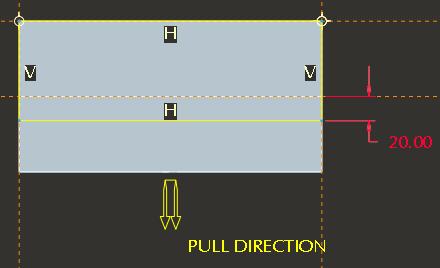
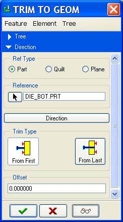
to start trimming the fixture
Select FIXTURE from the side menu,
DIE_BOT.PRT is the part that is used as the geometry for trim,
MAIN_PARTING_PLN is used for direction for the trim, and the arrow points down (Opposite direction as PULL_DIRECTION)

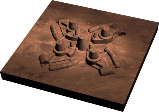
The cutout is created: RMB on BOT_PLATE.PRT and select OPEN to review this model:
Close this window to return the the main Cast MFG Assembly.
In the model tree, select BOT_PLATE.PRT, CULB_RESULT.PRT and DIE_BOT.PRT --> RMB and BLANK to hide the models.
Reproduce the steps before to now create the plate TOP_PLATE.PRT:
Cast Model > Create > Fixture,
create it as a SOLID PART named TOP_PLATE
Chose to LOCATE DEFAULT DATUMS and locate by THREE PLANES
Select the 3 first planes of the cast assembly (CAST_RIGHT, MAIN_PARTING_PLN, CAST_FRONT)
Sketch the extrusion profile:
Extrude to include all the bloc:
to start trimming the fixture:
WARNING: the part DIE_TOP.PRT is inappropriate for the cutout, we will have to COPY the external surfaces of this part WITHOUT the small hole that goes thru it... you COPY and PASTE and Cloe Loops to remove the hole.
Select FIXTURE from the side menu,
Select QUILT as you did a COPY of the skin surface of the model for trimming...
DIE_TOP.PRT is the part that is used as the geometry for trim,
MAIN_PARTING_PLN is used for direction for the trim, and the arrow points UP (same direction as PULL_DIRECTION)