Modifying dimensions in the 3D model
A new functionality of EMX5.0 is the ability to consider any modification made in the 3D model immediately in the EMX dialog boxes.
Activate the plate T1_CAV_PLATE_MH001.PRT.
Select the CHAMFER feature, open the Right Mousebutton Popup Menu and select Edit.
Overwrite the W1 value with 1.
Press Edit > Regenerate.
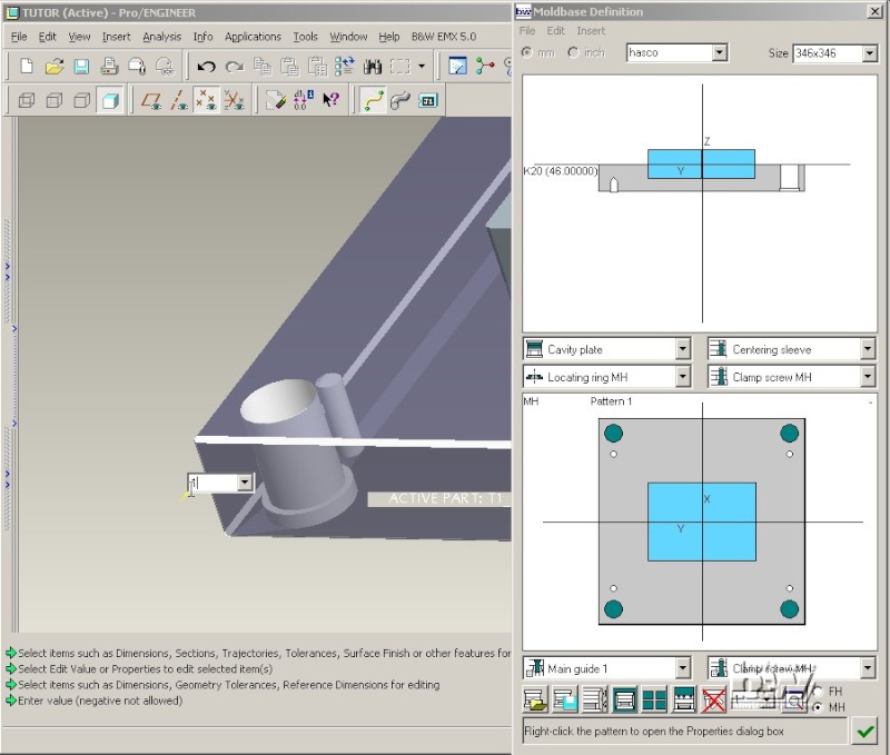
Rightclick the cavity plate in the side view of the Moldbase Definition dialog box.
Scroll the feature list until you can see the CHAMFER feature. The correct, current W1 value is shown.

Delete a plate
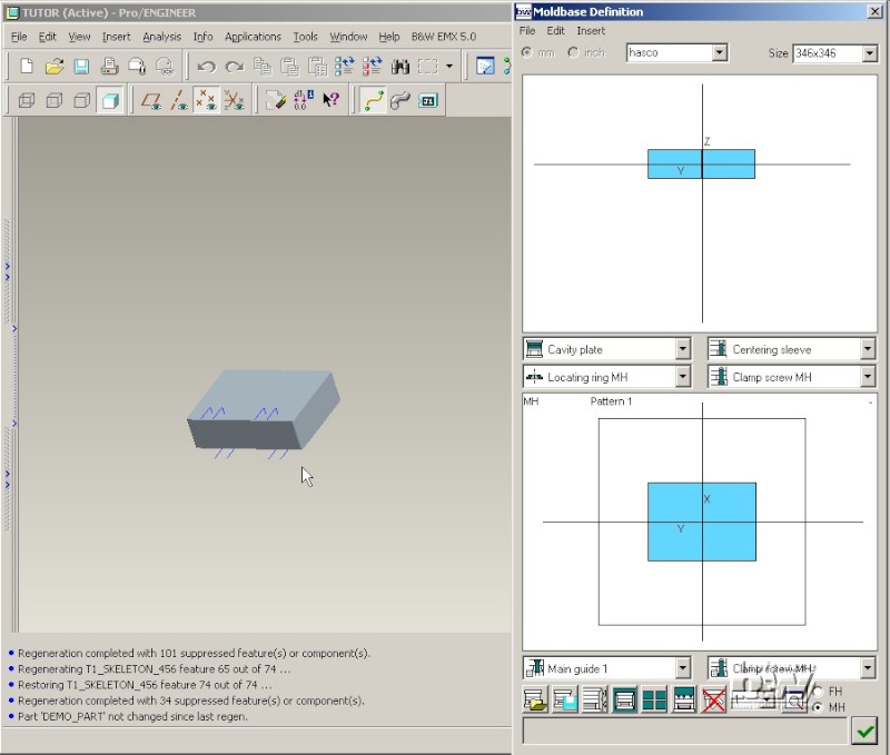
Click Edit > Delete the component in Moldbase Definition.
A red rectangle in the top left corner indicates that you have to select a component in the side view.
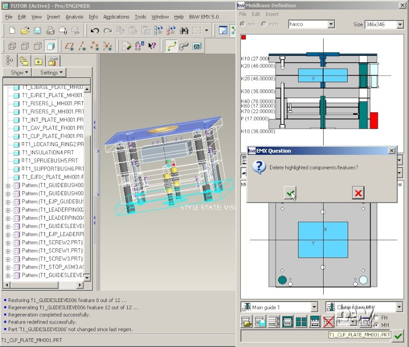
Click the K20 plate.
The plate gets displayed in red and an EMX Question Delete highlighted components/features appears.
Press (Yes).

The plate is removed in the Moldbase Definition and in the 3D model.
Note: Deleting a component is the only action in EMX that does not provide a preview.
Add Plates from different Suppliers
Select Clamping plate from the plate list.
Pick below the splitting plane.
Leave all entries in the plate dialog box to add a K10 clamping plate in the moving half.
Select Cavity plate form the plate list.
Pick the existing clamping plate K10.

The cavity plate is added between the selected plate and the splitting plane.
Click hasco and select supplier meusburger from the supplier list.
An new list Size will appear.
Click on this list and select size 346x446.

Select Plate type P.
Double click Thickness Value and select 66.000.

Note: Only P-plates can be used if the plate supplier differs from the supplier shown in Moldbase Definition. EMX would not be able to set proper pattern dimensions in this plates if the pattern dimensions for clamping screws and/or leaderpin cutouts are different for the two suppliers/sizes.
Close the Plate dialog box with .
Close Moldbase Definition with .
Check the content of the EMX Bill of Materials
Select EMX > Bill of Materials.
Click BOM List to verify that the different suppliers are set properly for both plates.

Close the Bill of Material dialog box with .
Manipulate Guide Components
One major improvement of EMX 5.0 is the flexibility of component manipulation. Even a component was defined in the Moldbase Definition dialog box its properties can be redefined using the direct access function EMX > [Component] > ...modify.
Redefine Properties in Moldbase Definition GUI
In HASCO moldbases the bushes and leader pins on one position of the leader pin pattern are usually different in size. (This helps to avoid wrong assembly of fix half and moving half). The model T1_GUIDESLEEVE006 is assembled at three instance of the leader pin pattern while T1_GUIDESLEEVE005 is assembled on just one instance.
Press EMX > Mold Base > Assembly Definition.
Rightclick on the left Guide Sleeve shown below. The color of the component and the leader pin pattern in the top view indicate where this component is assembled. The light green sleeve displayed in side view beside the moldbase is the component that is assembled just in one position.
Double click the Length Value in the Guides dialog box and select 100.

IMPORTANT NOTE: In any component dialog box the UDF's that will be created when adding the component are displayed (similar to the plate features) in the bottom part of the dialog box. The Overview sheet shows all dimensions for all cutouts while the Pre-, First-, Inter-, Last- and Post-Sheet show the individual UDF to be used in the related models. It is a kind of inconsistency in EMX that this UDF's do not matter for most components placed in Moldbase Definition. If a cutout (i.e. the thru holes for the guide sleeve) exist in the plates already (as they are defined in the plate properties), the UDF dimensions listed in the Guides dialog box do not matter at all. If the plates have NO cutouts when defining a new component (i.e. if the clamping plate is a P-plate) the cutouts are created using the component specific UDF's. In this case the dimensions of a cutout are driven by the component, not by the plate. As this issue is very important it is described in an extra chapter To Cut or not To Cut.
The new length is displayed in the Moldbase Definition preview.
Close the Guides dialog box with .
The length of the model T1_GUIDESLEEVE006 is set to 100 mm in the Pro/ENGINEER assembly.

Note: Compared to previous releases of EMX only this component is modifed when performing any action on it. All other settings of the 3D assembly remain.
Remove a Component in Moldbase Definition GUI
Select from Moldbase Definition dialog box.
Select the light green Guide sleeve displayed beside the moldbase.
Prompt the EMX Question with (Yes).
The Guide Sleeve T1_GUIDESLEEVE005 is removed.
Close Moldbase Definition with .
Redefine Properties using Guide Component > ...Modify
Make sure the display of Pro/ENGINEER datum points is set to Yes.
Select EMX > Guide Component > ...modify.
Select the datum point GUIDE_21 to modify the leader pin.

The Guide dialog box is opened displaying the current properties of the model T1_LEADERPIN002.
Double click Value of Lead Length and select 105.

Close the Guides dialog box with .
The leading length of the leader pin is set to 105 and the model is regenerated.