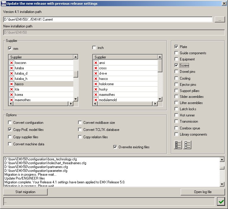
Copy Supplier Files
The available suppliers for certain components and the sort order that will appear in the supplier selection of all dialog boxes is defined in EMX 4.x by the supplier_*-files in <install_emx41>/tcltk/system/mm. In EMX5.0 the according supplier files are located in <install_exm50>/components/mm/<comp_type>. This option can only be used together with Copy ProE model files. Just activate also the Copy supplier files button before using Start migration.
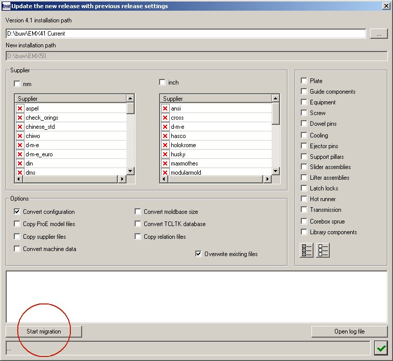
Convert Machine data
This option make sense as most customers have defined their own machine settings in previous EMX 4.x.
Activate mm and/or inch.
Activate Convert machine data.
Activate Overwrite existing files.
Press Start migration.
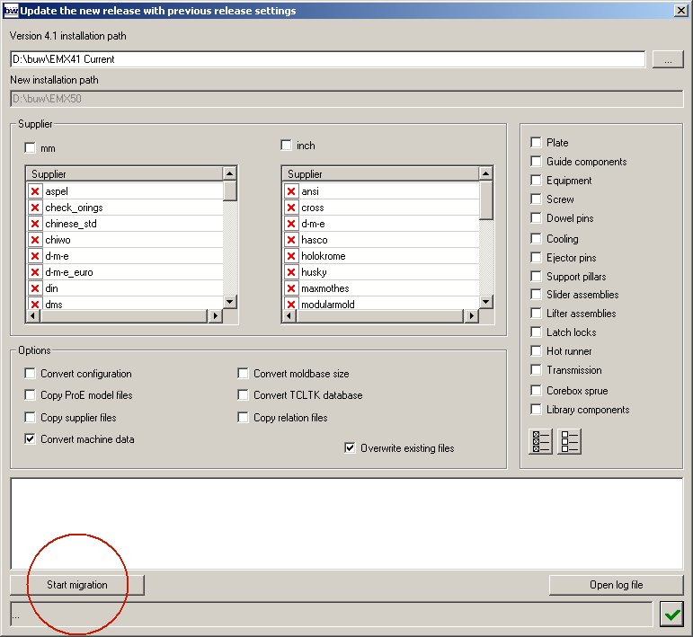
Note: Read EMX Machine Representation to improve and complete your converted machine data.
Convert Moldbase Sizes
Use this option only if you have added a new catalog in EMX 4.x or if you have modified the size-files for a supplier in <install_emx41>/tcltk/system/<supplier>/size_xxx.
Activate mm and/or inch.
Click any supplier from the list below mm to toggle its status to active.
Activate Convert moldbase size.
Activate Overwrite existing files.
Press Start migration.

All size-files of the selected suppliers will be transformed to match new EMX5.0 format. This reformatting was tested based on regular EMX supplier files only. Problems might occur if you use the function to convert your own catalog sizes.
Convert Component Data Files
If you had modified any data file in <install_emx41>/tcltk/system/<supplier>/mm use this dialog box to convert the files for EMX 5.0.
Activate mm and/or inch.
Click any supplier from the list below mm to toggle its status to activ.
Activate Convert moldbase size.
Activate Overwrite existing files.
Press Start migration.
This conversion is a very complex procedure as EMX 4.1 data files had a different format for each component type. In EMX5.0 the file format is identical for all components. If the EMX 5.0 data file created by this Conversion software seem to be incorrect read the Component Instances chapter. Based on that information you will be able to correct the files.
Copy Relation Files (not recommended)
EMX5.0 has a new approach to define the ordering numbers for all components. The relation files of EMX 4.x had been used to format the ordering numbers for components, but this had many disadvantages. In EMX5.0 the ordering number and other information can be defined for each instance in the database. Read the Component Instances chapter to learn more about this new approach.
EMX 5.0 Release Notes
This chapter describes the major modifications realized in EMX5.0. In addition to this points about 400 changes have been made to enhance work flow, user interface and Pro/ENGINEER models. When mentioning directory names in the following "mm" is used to describe unit specific directory names. If you work with imperial parts the according directories would be named "inch".
New Program Directory Structure
In release 4.1 the data of any EMX component had been stored in 4 different sub-directories of the EMX4.1 installation:
Suppliers: <install_emx41>/tcltk/system/mm
Component data: <install_emx41>/tcltk/system/<supplier>/mm/xxx_data.txt
Component models: <install_emx41>/mm/parts/<comptype>
Relations: <install_emx41>/mm/parts/<comptype>/<supplier>/mm
Therefore it was very complicated to add new components or maintain data files.
In EMX 5.0 all information regarding a certain component type (i.e. screws) is hosted in one directory
<install_emx50>/components/mm/<comptype>.
A unique Component Editor from EMX5.0 > Administrator Tools can be used to maintain the data files for all components in the future.
Note: In current release M020 of EMX 5.0 this Component Editor can only be used to add and maintain library components.
New Workflow
While defining properties of EMX components the Pro/ENGINEER window is no longer locked. Rotate your current design in the graphics window, toggle visibility of layers of features on and off, do any required action while defining EMX components. The major improvement was made in the Moldbase Definition dialog box: Only when loading an entire moldbase or change the moldbase size all components of the current 3D model will be modified. For any other modification only the part that was modified will be regenerated.
New GUI
All dialog boxes are now implemented using MS Windows API. This allow a direct link between Pro/ENGINEER and EMX dialog boxes without any intermediate files for data exchange that was required in 4.1 tcltk programing language. This direct link enables EMX 5.0 to provide a direct 3D-preview in the Pro/ENGINEER graphics window while defining the properties of a component.
The GUI layout is similar for all component types so it is very easy to learn how to use it.
Unique Component Data Format
The database of EMX 5.0 that contains all component relevant data is now identical for any EMX component. Read Component Instances for details.
New Handling of Component Bill of Material Information
All Bill of Material [BOM] information and naming conventions for a component are provided in the dialog box before the component is assembled. So it is possible to overwrite, correct the EMX defaults before this component will be added to your design.
The new Bill of Material dialog box provides access to each component of the EMX assembly. All parameters can be set individually. The parameters that are used to recognize identical components can be set up by the user. You can drive wether two components will be listed as one position in the BOM or as two positions.
Externalized description of Cutout Data
The link between a certain EMX component and the cutouts that are created for this components had been hard coded in EMX 4.1. The user had no chance to modify this but asking B&W for an enhancement request. In EMX 5.0 the information which cut should be made when placing a component is fully externalized in regular ascii files.
Please read Component Instances to get details.
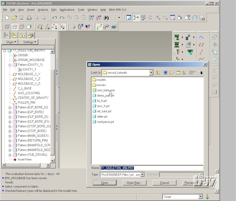
Using Skeleton models to support Subassemblies in EMX
As many companies like to work parallel with several designers on one mold design EMX 5.0 allow the setup of the moldbase using subassemblies. In the first step the main structure of the moldbase is defined in Moldbase Definition dialog box. Then all subassemblies can be modified individually using EMX in the further design. A skeleton model that contains all major datum references is inherited to all subassemblies.
Avoid Loss of References when Modifying Components
By default components and UDF's will no longer be disassembled when modify the properties of a EMX component. Even when changing the component type EMX will try to keep as much information of this component as possible to avoid unlinked dimensions in drawings or loss of component specific data.
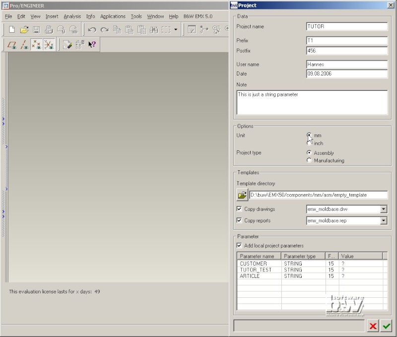
Support Project specific Parameters
In addition to default BOM parameters EMX does now support the definition of project specific BOM parameters such as article, customer name etc. in the Project Definition GUI. This parameter setup will be stored in the directory together with the moldbase assembly. When changing local parameters during the design process they will be updated in all existing parts of the assembly when opening the BOM dialog box.
Represent Machine by a Solid Model
In the EMX 4.1 assembly template the Mold injection machine was just represented just by some surface features. It was very hard to increase the information stored in the machine. In EMX 5.0 the Machine is represented by a real Pro/ENGINEER solid model. You can modify this model without limits and set up the dimensions that should be driven by the EMX Machine dialog box.
Note: As the model is part of the EMX assembly the outline of drawing views for this assembly will consider the machine representation. This enable the user to "fix" the drawing view outline so that views and snapping lines are no longer changed when adding plates. Just make sure the machine is larger than the moldbase stack of plates.
Improved Moldbase Opening Simulation
All Moldbase Opening Simulation tasks are driven by one dialog box in EMX 5.0. When running the simulation without interference check the time for calculating the single steps of the moldbase opening process had been reduced dramatically.
Further improvements
New SmartHolechart 5.0 is fully integrated in EMX 5.0. SmartHolechart functionality and usage is not part of this training guide. Please refer to the SmartHolechart Reference Guide for more information.
Set up user- or group specific configuration for EMX using the environment variables
EMX_USER_CONFIG_PATH for EMX settings and
SHC_USER_CONFIG for SmartHolechart settings.
Any EMX information (templates, data files, configuration files) can be hosted in this special EMX folders that must have the same directory structure like the default EMX installation.
Components that represent assemblies can be individually combined using previously defined component instances.
EMX will provide 5 functions for any type of component:
Define
Modify
Delete
Reassemble
Reassemble as Copy
New Analysis functions like Placement of QMM-points or Extracting the waterline will help to improve design quality.
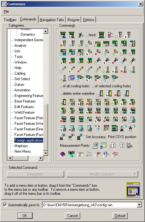
Set up the Bill of Material Parameters
When adding any EMX component a set of parameters will be added to the Pro/ENGINEER model and component. You can use this parameters to set up the columns of the Bill of Material [BOM].
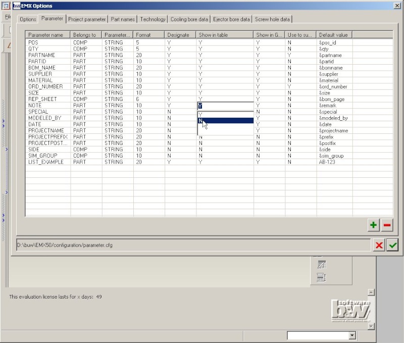
Select the Parameter Sheet in the EMX Options dialog box.

Remove a Parameter
Click the line DRW_SHEET.
This line will become the active (blue) line.

Press the button "-"
The parameter line will be removed from the list.
Disable a Parameter in the BOM Table
Double click the column Show in table in the line NOTE.
Select N from the list.
This parameter will now be created in each EMX part, but it will not be listed in the BOM table on the EMX report and drawing and in the EMX Bill of Material dialog box.
Add a New Project Parameter
Select the Project parameter Sheet in the EMX Options dialog box.
Click the line ARTICLE.
This line will become the active (blue) line.
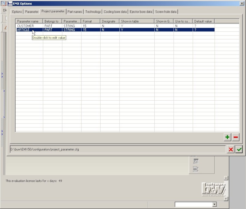
Press the button "+"
The content of the active line is copied to a new added parameter named _ARTICLE that appears above the active line.
Double click the first column of the line _ARTICLE.
Overwrite the name with TUTOR_TEST.
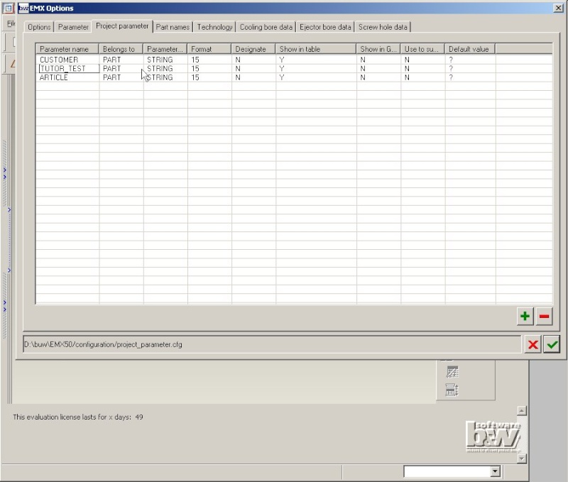
Leave the dialog box with to save the new settings.
The Option definition is saved to the file <install_emx50>/configuration/emx_options.cfg.
The Parameter definition is saved to the file <install_emx50>/configuration/parameter.cfg.
The Project parameter definition is saved to the file <install_emx50>/configuration/project_parameter.cfg.
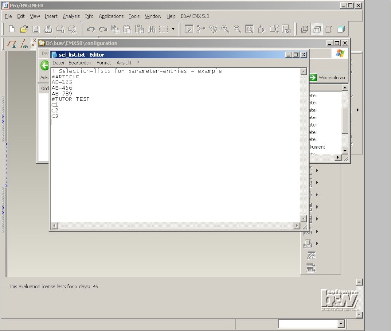
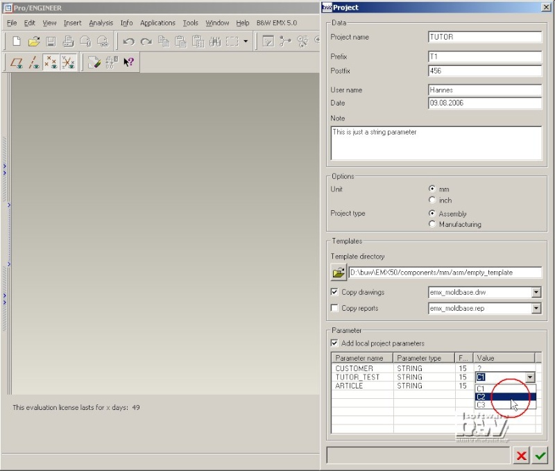
Predefine selection lists for parameters
For parameters that are not bound to an internal parameter in the Default value column (i.e. the new created parameter TUTOR_TEST) you can define a selection of valid values in the file <install_emx50>/configuration/sel_list.txt. Open this file with any editor (i.e. Notepad) and add the Parameter name with a "#" sign like shown below. Then list all possible values for this parameter in the following lines.